



- 机械工业出版社
- 9787111692409
- 1-2
- 67269927-9
- 16开
- 2021-10-22
- 装备制造大类
- 机械设计制造类
- 高职
内容简介
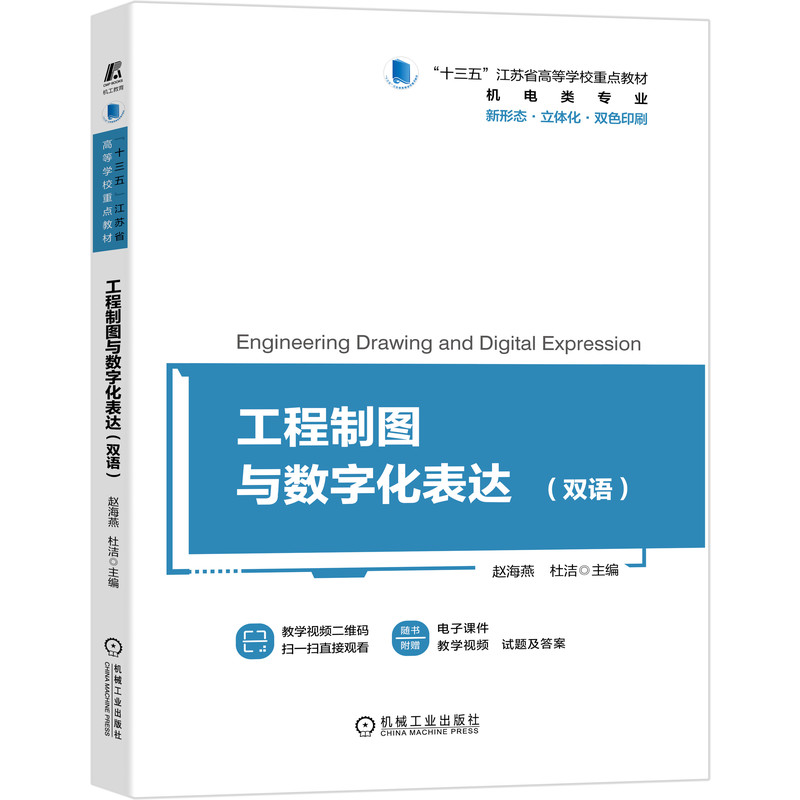
数字化是智能制造的基础。本书是为了满足智能制造对设计表达的数字化要求,根据现行的《技术制图》和《机械制图》国家标准编写而成的。本书吸收高等职业教育工程制图多年教学改革的经验,对传统教学内容进行了必要增减和优化整合,根据工作过程系统化和创新能力培养要求,将教学内容划分为7章,分别是产品设计与表达、计算机绘图、制图基础、机械制图标准、常用机件及结构要素的表示、零件图的识读与绘制、装配图的识读与绘制。
本书以培养学生的读图能力、数字化表达能力和创新能力为目标,提供大量带尺寸的立体图,有利于将知识的学习和技能的训练融为一体,实现学习和练习一体化、教材和习题集一体化,并通过在线开放课程网站提供补充习题,以满足不同学生、不同学校的需要。
Digitalization is the foundation of intelligent manufacturing. According to the current edition of Technical Drawings and Mechanical Drawings by national standard, this book aims to meet the digital requirements of intelligent manufacturing for design expression by utilizing experiences of higher vocational education educational reforms of Engineering Drawing. This book makes necessary adjustments and improvements to traditional teaching contents of mechanical drawing. To reflect and satisfy the requirements of systematic work process and innovative ability cultivation, this book divides its learning materials into seven chapters: product design and expression, computer graphics, fundamentals of drawing, standards of mechanical drawing, the representation of commonly-used machine parts and structural elements, the reading and drawing of the detail drawings, the reading and drawing of the assembly drawings.
This book aims to cultivate students' ability of drawing reading, digital expression and innovation.By providing a large number of 3D drawings labeled with sizes, it is beneficial to integrate the knowledge learning and skill training, and realizes the integration of textbook and problem set, as well as learning and practice. Moreover, the additional exercises are supplemented on the online open course website to meet the needs of different students and schools.
本书以培养学生的读图能力、数字化表达能力和创新能力为目标,提供大量带尺寸的立体图,有利于将知识的学习和技能的训练融为一体,实现学习和练习一体化、教材和习题集一体化,并通过在线开放课程网站提供补充习题,以满足不同学生、不同学校的需要。
Digitalization is the foundation of intelligent manufacturing. According to the current edition of Technical Drawings and Mechanical Drawings by national standard, this book aims to meet the digital requirements of intelligent manufacturing for design expression by utilizing experiences of higher vocational education educational reforms of Engineering Drawing. This book makes necessary adjustments and improvements to traditional teaching contents of mechanical drawing. To reflect and satisfy the requirements of systematic work process and innovative ability cultivation, this book divides its learning materials into seven chapters: product design and expression, computer graphics, fundamentals of drawing, standards of mechanical drawing, the representation of commonly-used machine parts and structural elements, the reading and drawing of the detail drawings, the reading and drawing of the assembly drawings.
This book aims to cultivate students' ability of drawing reading, digital expression and innovation.By providing a large number of 3D drawings labeled with sizes, it is beneficial to integrate the knowledge learning and skill training, and realizes the integration of textbook and problem set, as well as learning and practice. Moreover, the additional exercises are supplemented on the online open course website to meet the needs of different students and schools.
目录
Contents目 录
前言 Preface
第1章 产品设计与表达 Chapter 1 Product Design and Expression
1.1 产品表达方法 1.1 Representation of Products
1.2 工程图的作用 1.2 Functions of Engineering Drawings
1.3 课程任务 1.3 Course Tasks
1.4 学习方法 1.4 Learning Methods
[本章习题] [Chapter exercises]
第2章 计算机绘图 Chapter 2 Computer Graphics
2.1 计算机绘图概述 2.1 Computer Graphics Summary
2.2 体验Inventor 2.2 Experience Inventor
[本章习题] [Chapter exercises]
第 3章 制图基础 Chapter 3 Fundamentals of Drawing
3.1 正投影基本原理 3.1 Principle of Orthographic Projection
3.1.1 投影的概念及分类 3.1.1 Concept and Types of Projection
3.1.2 物体的三视图 3.1.2 Three-view Drawings
3.2 平面图形的分析 3.2 Analysis of Plane Figures
3.2.1 平面图形的尺寸分析 3.2.1 Dimensional Analysis of Plane Figure
3.2.2 平面图形的线段分析 3.2.2 Line Segment Analysis of Plane Figure
3.3 组合体的构形与分析 3.3 Configuration and Analysis of Composite Object
3.3.1 基本体与组合体 3.3.1 Basic Object and Composite Object
3.3.2 组合体的构形设计 3.3.2 Configuration Design of the Composite Object
[本章习题] [Chapter exercises]
第4章 机械制图标准 Chapter 4 Standards of Mechanical Drawing
4.1 机械制图国家标准的一般规定
4.1 General Provisions of National Standards of Mechanical Drawing
4.1.1 图纸幅面和格式(GB/T 14689—2008) 4.1.1 Drawing Sheet Size and Layout(GB/T 14689—2008)
4.1.2 比例(GB/T 14690—1993) 4.1.2 Scales(GB/T 14690—1993)
4.1.3 字体(GB/T 14691—1993) 4.1.3 Font(GB/T 14691—1993)
4.1.4 图线及画法(GB/T 4457.4—2002) 4.1.4 Lines and Drawing Techniques (GB/T 4457.4—2002)
4.1.5 尺寸注法(GB/T 4458.4—2003) 4.1.5 Dimensioning(GB/T 4458.4—2003)
4.2 机件表达方法 4.2 Representation of Machine Parts
4.2.1 视图 4.2.1 View
4.2.2 剖视图 4.2.2 Section View
4.2.3 断面图 4.2.3 Cross-section View
4.2.4 其他表达方法 4.2.4 Other Representation
4.3 技术要求 4.3 Technical Requirements
4.3.1 表面结构的表示法 4.3.1 The Representation of the Surface Structure
4.3.2 极限与配合 4.3.2 Limits and Fits
4.3.3 几何公差 4.3.3 Geometric Tolerance
[本章习题] [Chapter exercises]
第5章 常用机件及结构要素的表示 Chapter 5 The Representation of Commonly-used Machine Parts and Structural Elements
5.1 螺纹 5.1 Threads
5.1.1 螺纹概述 5.1.1 Threads Summary
5.1.2 螺纹的种类和标注 5.1.2 Types and Labeling of the Thread
5.2 螺纹紧固件 5.2 Thread Fastener
5.2.1 螺纹紧固件的标记 5.2.1 Labeling of Thread Fastener
5.2.2 螺纹联接 5.2.2 Thread Connection
5.3 键、销联接 5.3 Key and Pin Connection
5.3.1 键联接 5.3.1 Key Connection
5.3.2 销联接 5.3.2 Pin Connection 111
5.4 齿轮 5.4 Gear
5.4.1 直齿圆柱齿轮各部分名称和主要参数 5.4.1 Names and Major Parameters of Parts of Straight Toothed Spur Gear
5.4.2 各部分尺寸计算公式 5.4.2 Computational Formula of Part Dimensions
5.4.3 齿轮规定画法 5.4.3 Stipulated Drawing Method of the Gear
5.5 滚动轴承 5.5 Rolling Bearing
5.5.1 滚动轴承的种类 5.5.1 Types of Rolling Bearing
5.5.2 滚动轴承的代号(GB/T 272—2017) 5.5.2 Codes of Rolling Bearing (GB/T 272—2017)
5.6 弹簧 5.6 Spring
5.6.1 圆柱螺旋压缩弹簧各部分名称及尺寸计算 5.6.1 Names and Dimension Calculation of Different Parts of Cylindrical Helical Compression Spring
5.6.2 圆柱螺旋压缩弹簧的绘制 5.6.2 Drawing of Cylindrical Helical Compression Spring
[本章习题] [Chapter exercises]
第6章 零件图的识读与绘制 Chapter 6 The Reading and Drawing of the Detail Drawings 6.1 零件图的作用和内容 6.1 Function and Contents of Detail Drawings
6.1.1 零件图的作用 6.1.1 Function of Detail Drawings
6.1.2 零件图的内容 6.1.2 Contents of Detail Drawings
6.2 零件图的视图选择 6.2 Choosing Views of Detail Drawings
6.2.1 主视图的选择 6.2.1 Choosing the Front View
6.2.2 其他视图的选择 6.2.2 Choosing Other Views
6.2.3 典型零件分析 6.2.3 Analysis of Typical Parts
6.3 零件图的尺寸标注 6.3 Dimensioning of Detail Drawings
6.3.1 尺寸基准的选择 6.3.1 Selection of Dimensioning Datum
6.3.2 尺寸标注方法 6.3.2 Dimensioning Method
6.3.3 零件上常见结构的尺寸标注 6.3.3 Dimensioning of Common Structures on Parts
6.4 零件上常见的工艺结构 6.4 Common Process Structure on Parts
6.4.1 铸造结构 6.4.1 Casting Structure
6.4.2 机械加工零件的工艺结构 6.4.2 Process Structure of Machined Parts
6.5 读零件图 6.5 Interpreting Detail Drawings
6.5.1 概述 6.5.1 Summary
6.5.2 分析视图 6.5.2 View Analysis
6.5.3 分析尺寸 6.5.3 Analyzing Dimensions
6.5.4 了解技术要求 6.5.4 Understanding Technical Requirements
6.5.5 综合分析 6.5.5 Comprehensive Analysis
6.6 绘制零件图 6.6 Drawing Detail Drawings
[本章习题] [Chapter exercises]
第7章 装配图的识读与绘制 Chapter 7 The Reading and Drawing of the Assembly Drawings
7.1 装配图的内容 7.1 Contents of Assembly Drawings
7.2 装配图的尺寸标注、技术要求和零件编号 7.2 Dimensioning of Assembly Drawings, Technical Requirements and Part Numbers
7.2.1 装配图的尺寸标注 7.2.1 Dimensioning of Assembly Drawings
7.2.2 装配图的技术要求 7.2.2 Technical Requirements of Assembly Drawings
7.2.3 装配图的零件序号和明细栏 7.2.3 Part Numbers and Part Lists of Assembly Drawings
7.3 装配图的表达方法 7.3 Representation Methods of Assembly Drawings
7.3.1 规定画法 7.3.1 Conventional Representation
7.3.2 特殊表达方法 7.3.2 Special Representation Methods
7.4 装配图的绘制 7.4 Assembly Drawing
7.4.1 部件装配关系分析 7.4.1 Analysis of Subassembly Assembly Relationship
7.4.2 部件装配 7.4.2 Subassembly Assembly
7.4.3 装配图的表达方案 7.4.3 Representation Method of Assembly Drawing
7.4.4 绘制装配图 7.4.4 Drawing of Assembly Drawing
7.5 装配结构的合理性 7.5 Rationality of Fitting Structure
7.5.1 相邻两零件的接触面 7.5.1 Contact Surface of Two Adjacent Parts
7.5.2 轴与孔配合 7.5.2 Fitting of Shafts and Holes
7.5.3 拆装空间 7.5.3 Space for Disassembly
7.5.4 防松结构 7.5.4 Anti-loosening Structure
7.5.5 轴向固定结构 7.5.5 Axial Fixed Structure
7.6 读装配图 7.6 Reading Assembly Drawings
7.6.1 读装配图的方法和步骤 7.6.1 Methods and Steps of Reading Assembly Drawings
7.6.2 由装配图拆画零件图 7.6.2 Extracting Part Drawing from Assembly Drawing
[本章习题] [Chapter exercises]
参考文献 References
前言 Preface
第1章 产品设计与表达 Chapter 1 Product Design and Expression
1.1 产品表达方法 1.1 Representation of Products
1.2 工程图的作用 1.2 Functions of Engineering Drawings
1.3 课程任务 1.3 Course Tasks
1.4 学习方法 1.4 Learning Methods
[本章习题] [Chapter exercises]
第2章 计算机绘图 Chapter 2 Computer Graphics
2.1 计算机绘图概述 2.1 Computer Graphics Summary
2.2 体验Inventor 2.2 Experience Inventor
[本章习题] [Chapter exercises]
第 3章 制图基础 Chapter 3 Fundamentals of Drawing
3.1 正投影基本原理 3.1 Principle of Orthographic Projection
3.1.1 投影的概念及分类 3.1.1 Concept and Types of Projection
3.1.2 物体的三视图 3.1.2 Three-view Drawings
3.2 平面图形的分析 3.2 Analysis of Plane Figures
3.2.1 平面图形的尺寸分析 3.2.1 Dimensional Analysis of Plane Figure
3.2.2 平面图形的线段分析 3.2.2 Line Segment Analysis of Plane Figure
3.3 组合体的构形与分析 3.3 Configuration and Analysis of Composite Object
3.3.1 基本体与组合体 3.3.1 Basic Object and Composite Object
3.3.2 组合体的构形设计 3.3.2 Configuration Design of the Composite Object
[本章习题] [Chapter exercises]
第4章 机械制图标准 Chapter 4 Standards of Mechanical Drawing
4.1 机械制图国家标准的一般规定
4.1 General Provisions of National Standards of Mechanical Drawing
4.1.1 图纸幅面和格式(GB/T 14689—2008) 4.1.1 Drawing Sheet Size and Layout(GB/T 14689—2008)
4.1.2 比例(GB/T 14690—1993) 4.1.2 Scales(GB/T 14690—1993)
4.1.3 字体(GB/T 14691—1993) 4.1.3 Font(GB/T 14691—1993)
4.1.4 图线及画法(GB/T 4457.4—2002) 4.1.4 Lines and Drawing Techniques (GB/T 4457.4—2002)
4.1.5 尺寸注法(GB/T 4458.4—2003) 4.1.5 Dimensioning(GB/T 4458.4—2003)
4.2 机件表达方法 4.2 Representation of Machine Parts
4.2.1 视图 4.2.1 View
4.2.2 剖视图 4.2.2 Section View
4.2.3 断面图 4.2.3 Cross-section View
4.2.4 其他表达方法 4.2.4 Other Representation
4.3 技术要求 4.3 Technical Requirements
4.3.1 表面结构的表示法 4.3.1 The Representation of the Surface Structure
4.3.2 极限与配合 4.3.2 Limits and Fits
4.3.3 几何公差 4.3.3 Geometric Tolerance
[本章习题] [Chapter exercises]
第5章 常用机件及结构要素的表示 Chapter 5 The Representation of Commonly-used Machine Parts and Structural Elements
5.1 螺纹 5.1 Threads
5.1.1 螺纹概述 5.1.1 Threads Summary
5.1.2 螺纹的种类和标注 5.1.2 Types and Labeling of the Thread
5.2 螺纹紧固件 5.2 Thread Fastener
5.2.1 螺纹紧固件的标记 5.2.1 Labeling of Thread Fastener
5.2.2 螺纹联接 5.2.2 Thread Connection
5.3 键、销联接 5.3 Key and Pin Connection
5.3.1 键联接 5.3.1 Key Connection
5.3.2 销联接 5.3.2 Pin Connection 111
5.4 齿轮 5.4 Gear
5.4.1 直齿圆柱齿轮各部分名称和主要参数 5.4.1 Names and Major Parameters of Parts of Straight Toothed Spur Gear
5.4.2 各部分尺寸计算公式 5.4.2 Computational Formula of Part Dimensions
5.4.3 齿轮规定画法 5.4.3 Stipulated Drawing Method of the Gear
5.5 滚动轴承 5.5 Rolling Bearing
5.5.1 滚动轴承的种类 5.5.1 Types of Rolling Bearing
5.5.2 滚动轴承的代号(GB/T 272—2017) 5.5.2 Codes of Rolling Bearing (GB/T 272—2017)
5.6 弹簧 5.6 Spring
5.6.1 圆柱螺旋压缩弹簧各部分名称及尺寸计算 5.6.1 Names and Dimension Calculation of Different Parts of Cylindrical Helical Compression Spring
5.6.2 圆柱螺旋压缩弹簧的绘制 5.6.2 Drawing of Cylindrical Helical Compression Spring
[本章习题] [Chapter exercises]
第6章 零件图的识读与绘制 Chapter 6 The Reading and Drawing of the Detail Drawings 6.1 零件图的作用和内容 6.1 Function and Contents of Detail Drawings
6.1.1 零件图的作用 6.1.1 Function of Detail Drawings
6.1.2 零件图的内容 6.1.2 Contents of Detail Drawings
6.2 零件图的视图选择 6.2 Choosing Views of Detail Drawings
6.2.1 主视图的选择 6.2.1 Choosing the Front View
6.2.2 其他视图的选择 6.2.2 Choosing Other Views
6.2.3 典型零件分析 6.2.3 Analysis of Typical Parts
6.3 零件图的尺寸标注 6.3 Dimensioning of Detail Drawings
6.3.1 尺寸基准的选择 6.3.1 Selection of Dimensioning Datum
6.3.2 尺寸标注方法 6.3.2 Dimensioning Method
6.3.3 零件上常见结构的尺寸标注 6.3.3 Dimensioning of Common Structures on Parts
6.4 零件上常见的工艺结构 6.4 Common Process Structure on Parts
6.4.1 铸造结构 6.4.1 Casting Structure
6.4.2 机械加工零件的工艺结构 6.4.2 Process Structure of Machined Parts
6.5 读零件图 6.5 Interpreting Detail Drawings
6.5.1 概述 6.5.1 Summary
6.5.2 分析视图 6.5.2 View Analysis
6.5.3 分析尺寸 6.5.3 Analyzing Dimensions
6.5.4 了解技术要求 6.5.4 Understanding Technical Requirements
6.5.5 综合分析 6.5.5 Comprehensive Analysis
6.6 绘制零件图 6.6 Drawing Detail Drawings
[本章习题] [Chapter exercises]
第7章 装配图的识读与绘制 Chapter 7 The Reading and Drawing of the Assembly Drawings
7.1 装配图的内容 7.1 Contents of Assembly Drawings
7.2 装配图的尺寸标注、技术要求和零件编号 7.2 Dimensioning of Assembly Drawings, Technical Requirements and Part Numbers
7.2.1 装配图的尺寸标注 7.2.1 Dimensioning of Assembly Drawings
7.2.2 装配图的技术要求 7.2.2 Technical Requirements of Assembly Drawings
7.2.3 装配图的零件序号和明细栏 7.2.3 Part Numbers and Part Lists of Assembly Drawings
7.3 装配图的表达方法 7.3 Representation Methods of Assembly Drawings
7.3.1 规定画法 7.3.1 Conventional Representation
7.3.2 特殊表达方法 7.3.2 Special Representation Methods
7.4 装配图的绘制 7.4 Assembly Drawing
7.4.1 部件装配关系分析 7.4.1 Analysis of Subassembly Assembly Relationship
7.4.2 部件装配 7.4.2 Subassembly Assembly
7.4.3 装配图的表达方案 7.4.3 Representation Method of Assembly Drawing
7.4.4 绘制装配图 7.4.4 Drawing of Assembly Drawing
7.5 装配结构的合理性 7.5 Rationality of Fitting Structure
7.5.1 相邻两零件的接触面 7.5.1 Contact Surface of Two Adjacent Parts
7.5.2 轴与孔配合 7.5.2 Fitting of Shafts and Holes
7.5.3 拆装空间 7.5.3 Space for Disassembly
7.5.4 防松结构 7.5.4 Anti-loosening Structure
7.5.5 轴向固定结构 7.5.5 Axial Fixed Structure
7.6 读装配图 7.6 Reading Assembly Drawings
7.6.1 读装配图的方法和步骤 7.6.1 Methods and Steps of Reading Assembly Drawings
7.6.2 由装配图拆画零件图 7.6.2 Extracting Part Drawing from Assembly Drawing
[本章习题] [Chapter exercises]
参考文献 References
